
Pelton Turbine Working, Main Parts, Application with Diagram Mechanical Booster
The Pelton wheel or Pelton turbine is an impulse type water turbine invented by American inventor Lester Allan Pelton in the 1870s. The Pelton wheel extracts energy from the momentum of the moving water, as opposed to the water's own weight like the traditional overshot water wheel. There were many earlier variations of impulse turbines, but.

7. STUDY PERFORMANCE CHARACTERISTICS TEST OF A PELTON TURBINE.
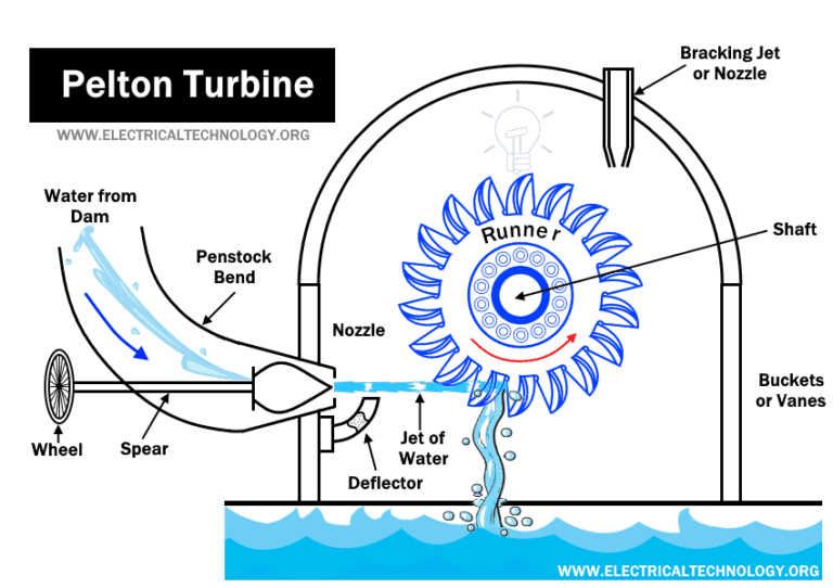
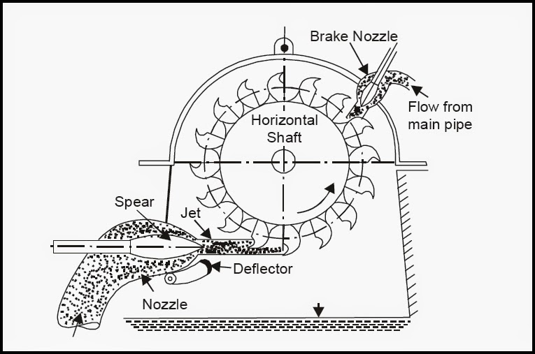
Working of Pelton turbine. Above image shows a cross sectional diagram of a Pelton wheel. Since a Pelton turbine requires a very high head for operation, it results into very high energy water jet. This jet is made to strike on the Pelton wheel. In a single impulse, all the kinetic energy of jet gets transferred to the Pelton wheel.

Pelton Turbine (Pelton Wheel) Explained saVRee saVRee
Francis Turbine Working Principle, Main Parts, Diagram and Application What is Reaction Turbine - Principle, Working, Main Components and Application 2. Runner and Buckets The runner with buckets is shown in the figure given below. Runner is a rotating part of the turbine.

Governing of Pelton Wheel Turbine With Animation YouTube
Figure 5.3.2.3 5.3.2. 3: The Pelton turbine also uses elements that act as "turnarounders" of water streams hitting them. They are called "buckets" and a number of them is mounted at the perimeter of the runner. The water jet hits the "ridge" in the bucket's center and is split into two streams that are both turned around (source.

Pelton Turbine Working, Main Parts, Application with Diagram Mechanical Booster
Water turbines are critical in mankind's pursuit of clean energy. Among these, the Pelton turbine, inspired by the ingenuity of Lester Pelton, shines for its simplicity and power, which make it especially suitable for extracting energy from high-altitude water sources.
Hydropower Plant Types, Components, Turbines and Working
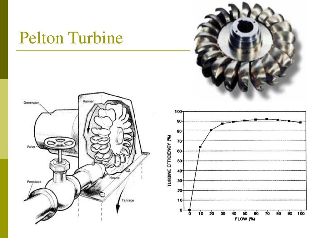
A basic diagram of a Pelton turbine is shown in Figure 1, and a rotor (this is the so-called 'Pelton wheel') is shown in Figure 2. Diagram of Pelton turbine main parts In Figure 1 the penstock pipe delivers the water on the left-hand side.

Construction and Working of Pelton Wheel
1. Diagram and animation of Pelton wheel turbine. 2. Introduction of Pelton wheel turbine..more.more Voith: Functioning of Pelton turbines (EN) Francis turbine 57K views 4 years.

Pelton wheel turbine with generalized velocity diagram in Hindi. Explain pelton wheel turbine
The design of a Pelton turbine starts with the dimensioning of the Pelton wheel, the choice of the rotational speed, and the determination of the number of injectors. To this end the following indications arising from the practical operations of Pelton turbines aid in establishing the design procedure:

Pelton Wheel Turbine YouTube
Among different types of impulse turbines, Pelton wheel is the only turbine beingused at present. It was discovered in 188 0 by an American Engineer LesterA. Pelton. It operates under v ery high heads (upto 1800 m) and requires comparatively lesser quantity of water. Working principle of Pelton turbines From the head race in the mountains water.

Pelton Wheel Turbine Parts, Working, Efficiency, Advantages, Disadvantages, Applications [With
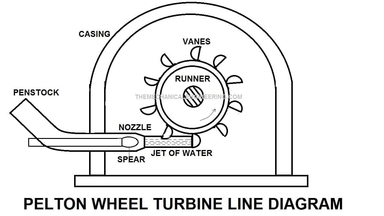
The turbine consists of a number of buckets (also called cups) rigidly connected to the periphery of a wheel. Water is conveyed from a reservoir to the turbine through penstocks. The penstock is connected to a pipe or branch pipes fitted with nozzles. The powerful jet issuing from the nozzle impinges tangentially on the buckets.
PPT MICRO HYDROELECTRIC POWER PLANT WITH CHAIN TURBINE PowerPoint Presentation ID341600
The turbine has been designed for the operational conditions of the Pelton test rig installed at the Waterpower Laboratory which is a horizontal single jet test rig with a jet diameter (ds) of 35.
Principal scheme of the Pelton turbine. Download Scientific Diagram
A Pelton wheel turbine is a tangential flow turbine in which the pressure energy of water is transformed into kinetic energy to form a high-speed water jet and this water jet hits the wheel tangentially to rotate it. An American developer Lester Allan Pelton invented the Pelton wheel turbine in the 1870s.
Engineering projects Pelton Turbine
1. Nozzle and flow regulating arrangement : 2. Runner with Buckets : 3. Casing : 4. Breaking jet: 5. Governing mechanism: Working of Pelton wheel: Velocity Triangles Diagram For Pelton Wheel : Pelton Wheel - Efficiencies and Work done Design Of Pelton Wheel : Performance and operating characteristics curves of a Pelton turbine :

5. Typical layout of a modern Pelton turbine (Ecopolis 2010). Download Scientific Diagram
Basic diagrams of a Pelton and Francis turbine are shown in Fig. 8. The dimensions of the Pelton turbine can be estimated if the runner speed (N), the net head (H) and water flow rate (Q).
Pelton Wheel Turbine Definition, Parts, Working Principle, Advantages, Application [Notes & PDF]
The Pelton wheel or Pelton Turbine is an impulse -type water turbine invented by American inventor Lester Allan Pelton in the 1870s. [1] [2] The Pelton wheel extracts energy from the impulse of moving water, as opposed to water's dead weight like the traditional overshot water wheel.

Velocity Triangles Diagram For Pelton Wheel of Impulse Turbine Thermal Engineering Shubham
Pelton Wheel Turbine is an impulse turbine designed to harness water energy in high head applications for power generation. In this turbine, a high-velocity jet of water exits the nozzle and strikes the open air, subsequently impacting the specially designed buckets or vanes.